Material Properties
Material properties are at the heart of whether a given part/specimen will fail under certain loading conditions. This is an important consideration when designing a trebuchet. There are a number of parts that are critical to the strength of a design, and if the material is not chosen properly, or the part is not designed correctly, the part can fail. The most common failure part in a trebuchet is the main axle. But before discovering whether parts will fail or not, a good understanding of how materials behave under stress is useful. This section will not get into heavy detail down to the molecular level, but will suffice to provide a general understanding of the material properties pertinent to trebuchet design, particularly axles. For a more thorough investigation into material properties and the behavior of materials under loading, there are plenty of good engineering books around that cover this area.
So, let's take a very simple case, and one that is used quite extensively for determining material strength. This test takes a specimen, typically round with a narrowed down central portion, of the material to be tested. The dimensions of such test specimens are regulated by testing standards, but are unimportant for the discussion here. Two marks (small dimples, usually, created gently with a punch, but can be done with a fine-tipped marker or such), are placed on the narrowed section of the specimen, typically a basic distance apart (say 4 inches), and roughly centered on the narrowed length, away from the transition section of the specimen where the diameter changes. An instrument called an extensometer is placed on the specimen in this region. The specimen is then mounted in the testing machine.
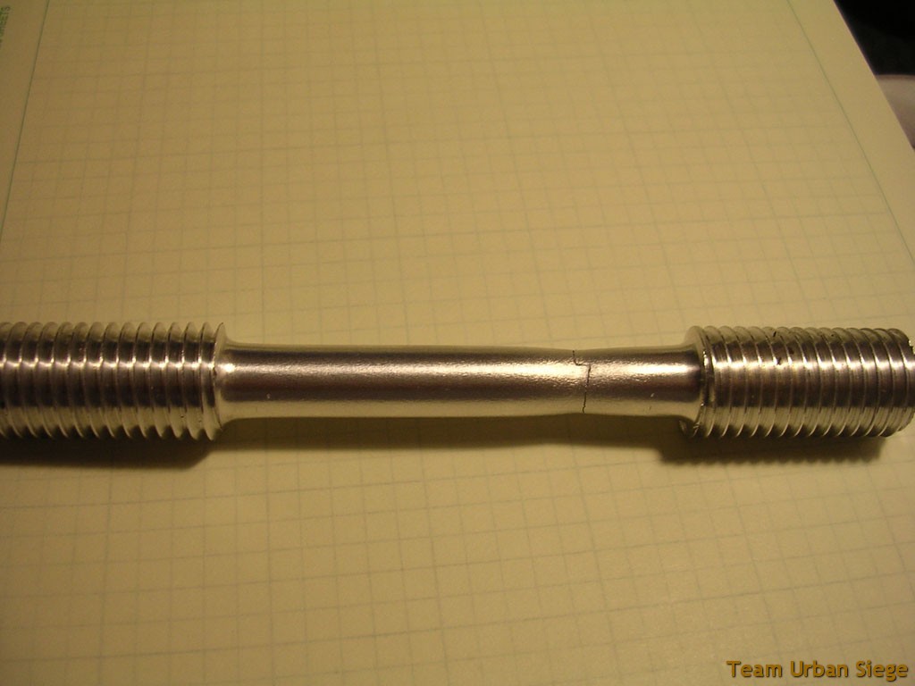
An aluminum tensile test specimen. This is an already tested part as can be seen by the crack on the right side, but you still get the idea.
By hooking up the extensometer to a data acquisition system, the strain in the part can be measured during the elastic region (more on this later). At the same time, the load applied is measured. To test the part, the specimen is stretched at a gradual speed, with the values of the load and strain being measured along the way. Eventually, the part will develop a drastic reduction in cross-sectional area, called necking. Note the picture above around the failure point. You can see that the diameter around the failure area is significantly reduced. Despite this dramatic reduction in area, the load will increase very little if at all. By this point the extensometer is removed to avoid damage. Shortly thereafter, the part will fail (with a very loud bang as a lot of strain energy is released).
Stress in a part under tensile loading is defined by the relation σ=P/A, where P is the applied axial load and A is the cross-sectional area. σ is the standard symbol for normal stress, which is what an axial load produces. Thus, for all of the data points recorded during the test, the axial stress can be computed. Plotting the stress against the strain yields what is referred to as a stress-strain curve, and these curves tell a lot of information about the strength of the material. Such a curve will look something like the following:
Now, the actual shape of the curve will vary with material, but this general shape will hold true for any ductile material. A ductile material is one that elongates by at least 5% before failing. Believe it or not, steel is such a material, as is aluminum and pretty much every metal. A brittle material is one that does not exhibit the necking mentioned earlier. It also shows a much different type of curve, one that might look something more like the following:
Notice that for the brittle material (concrete, ceramics, etc), the curve ends right around its peak, instead of declining off of it for a while, like the ductile material does. Points 2 and 3 are also usually pretty close together, instead of fairly far apart as shown in this diagram just for clarity. In the case of both curves, point 3 is called the ultimate strength of the material, while point 4 is the fracture strength (strength is used interchangeably with stress here). The ultimate strength/stress is the maximum stress that the material will take, while the fracture strength/stress is the stress at which the material fails after experiencing the ultimate stress. For brittle materials, these two strengths are nearly identical, and so usually only one will be listed. For ductile materials, which experience necking, these points are separated a bit. Necking occurs at point 3. The stress then drops off, while the material continues to elongate. Since strain is directly related to the amount of elongation (specifically, strain is the ratio of the elongation divided by the initial length-recall the gage length mentioned earlier), this continued elongation results in a continuing increase in strain, hence the nature of the descending curve beyond point 3.
Point 2 is more interesting, and perhaps the most important. Point 2 is what is referred to as the yield strength/stress. Note the linear nature of the curve below this point. Any stress applied to the material in this region, and then removed, will result in no net deformation of the material. Put another way, loads in this region do not permanently deform the part. This portion of the curve is called the elastic region, owing to the elastic nature of the material returning to its original state under stresses here. The slope of this portion has a special name, called either the Elastic Modulus, or Young's Modulus, or even the Modulus of Elasticity. This is typically denoted by the letter 'E'. Thus, this portion of the graph can be expressed in the form σ=Eε, where ε is the strain. Those familiar with spring forces will recognize this relation as Hooke's Law (presented as F=kx).
In reality, most parts in a pure tensile test such as the one described here will fail along a 45° plane (relative to the main axis). As a result, the failed part exhibits a cup-and-cone feature at the failure point. However, the ultimate stress found under such a test is the stress at which the part fails in shear, which is oriented 45° to the main axis. Shear stress will not be covered here, but be aware that it does exist.
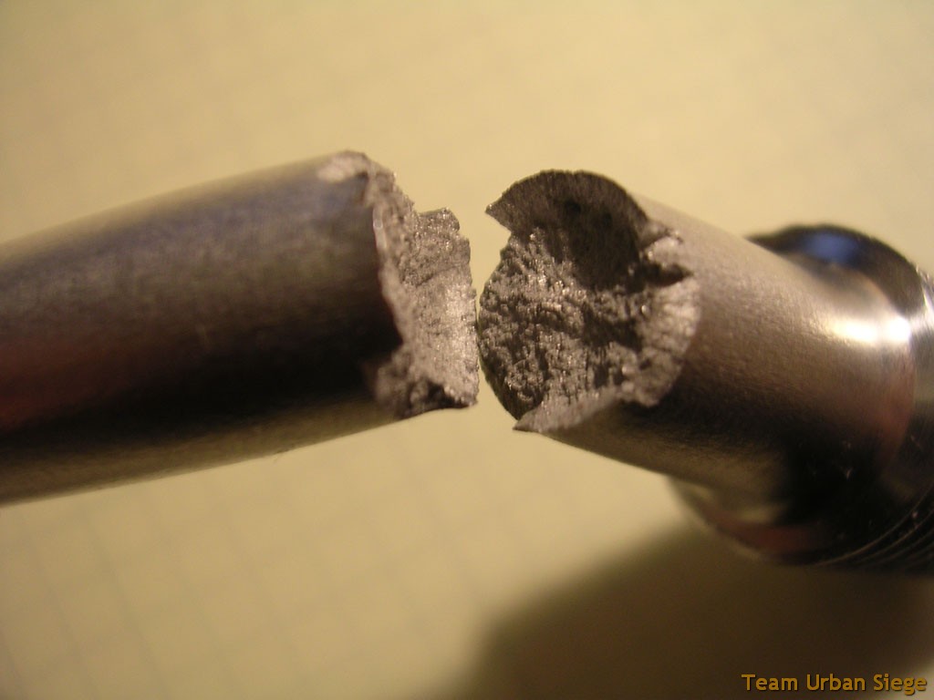
Here you can somewhat see the cup-and-cone fracture surface of the test specimen; the break is at an angle to the main axis of the part as opposed to perpendicular as one might expect.
What is important here for designing is not so much the ultimate strength, but the yield strength. While one could design to the ultimate strength, quite an extensive deformation of the part will likely occur, which can cause problems. The safest route is to design to the yield strength, as staying below this point will ensure no permanent deformation. Further, elastic deformations in this range are typically quite minor, especially for steel. We recommend designing to the yield strength, and throwing in a factor of safety of at least 1.5, if not 2. This means that, if the expected stresses in the part are around 15,000 psi, make sure the material yield will be at least 22,500 psi, or even 30,000. One could also design for a given material, sizing the part to keep the factor of safety at least 1.5. It doesn't matter which way you design, and often a combination of both may be needed. There are a couple of reasons for using a factor of safety, however, no matter the method it is used in.
One is that the yield strength is slightly imprecise. When the test data of stress versus strain is plotted, the data will naturally not be all along the exact same line. Therefore, the yield strength is usually determined by the point at which the curve deviates from the elastic line by 0.2%. Put another way, if a linear line is plotted for the data that is clearly linear and not right near the deviation point, you can determine the Elastic Modulus. This line should pass through the origin (after all, if no stress is applied, there shouldn't be any elongation. If another line is drawn parallel to this one (that is, with the same slope), but passing through the strain axis where strain is 0.2%, the point at which this line intersects the data curve will determine the yield strength. There is some imprecision at this point, and so a factor of safety relative to it should avoid any issues with the inaccuracies. Furthermore, slight material defects can alter the yield strength from part to part.
An example of how the yield stress is determined from actual experimental data for an Aluminum 2024-T4 specimen. Note how the yield strength is determined.
The other big reason to ensure a factor of safety relative to the yield strength has to do with fatigue. Whether they realize it or not, nearly everyone understands this concept. When you need to bend a piece of metal with only your bare hands, usually you will bend it back and forth over and over until it breaks. This repetitive motion fatigues the part. It survives the first cycle usually, and often many more, but will eventually break. If the stress is kept under the yield strength by at least a factor of safety of 1.5, the fatigue strength (the stress at which the part will fail under a certain number of cycles at that stress) will not be for thousands, if not tens of thousands or more cycles. With a factor of safety of 2 or more to the yield point, the part is likely to exhibit infinite life, which is defined by surviving at least 1 million cycles. This is not likely to be an issue on a trebuchet, then. One thing to note is that aluminum does not reach and endurance strength, but it does see a reduced strength over time and as such is even more tricky than steel in that regard. Still, under the minimal cycles a trebuchet sees, this should not pose an issue when parts tend to be replaced every few years anyway. Just be careful when using aluminum, basically.
One not concerning the test method described above. It is for a tensile test, however, for ductile materials, the yield/ultimate strength are typically the same in compression. Since on a symmetric beam (like the round bar used most often for a trebuchet axle) the top surface is in compression while the bottom is in tension (with a vertical load directed downward on the beam of course), this attribute is important. For brittle materials, like concrete, the ultimate strength in compression is much higher than in tension.
So now that we know about ultimate strength, yield strength, and the like, how about some typical values? Well, steel is the most common material for a trebuchet axle due to its availability, and strength. Weight typically isn't an issue with an axle on such machines, though in other applications it can be. But either way, there are many different types of steel. A standard low-carbon steel such as AISI 1018 is what you are likely to find most common, and has a yield on the order of 30,000 psi. By contrast, an alloy steel that adds in more than just carbon (which is what the low-grade steels do: a small percentage of carbon mixed in with iron) can have yields well over 100,000 psi! 1144 is such a steel, depending on the method used. In many ways, the method used to make the material is more important to the yield strength than the actual material composition, although it helps too. For example, a cold-rolled 1144 steel bar will only have a yield around 50,000 psi or so, a dramatic difference from the heat-treated versions that can top 100,000 psi. If you have a piece of steel from a random place such as Home Depot, or is scrap that you have no idea what the exact type is, assume the yield is around 30,000 psi, because more likely than not it is cold-rolled 1018 steel or equivalent. General aluminum commonly available is either 6061-T6 or 6063 most often. The 6061-T6 has a yield in excess of 30,000 psi, while 6063 is only 15,000 or 20,000 depending on the source you look at.
A good resource for looking up the material properties of a material is the site Matweb. It has a free to view database of material properties for everything from steel to rubber and all in between. They will have a yield for nearly every material, and often multiple are listed. Read the notes on each page about the properties. There are a number of other sites too. One thing to note is that the site will generally report stresses in ksi (for the Imperial system, kPa or MPa for Metric). One ksi is equivalent to 1000 psi. Therefore, a 30 ksi yield strength means 30,000 psi.